Page 46 of 124
Re: 1967 Family Patrol Project
Posted: Wed Aug 20, 2014 9:22 am
by bosque
Good read. Do you have a picture of your set up to share? The harness sounds like a couple wires and not much more......$100.....?

J,
This does make sense but I always have to scrutinize a mod (and in this case observe Aerogirl as guinea pig, thanks).....I mean seriously.....the engineers were smart dudes although old school! Forge on and after you succeed please reengineer the rear seal.


Re: 1967 Family Patrol Project
Posted: Wed Aug 20, 2014 10:17 am
by faux40
Esteban wrote:
I've been running 100 watt bulbs (don't tell Robert, please

) inside the headlamps of my Patrol for over 20 years, and the switch is still the original one from almost 50 years! After reading your post, I think I will need to do an intervention in this department also, since they're putting the same illumination as a regular headlamp of other cars.
Please post part numbers for the relays and their sockets.
Esteban, I suspect you forgot your decimal point on your previous post. I'm sure you meant "10.0 watt bulbs" --

I bought these five for at total of $14:
http://www.amazon.com/gp/product/B005HFYE1O
bosque wrote:Do you have a picture of your set up to share? The harness sounds like a couple wires and not much more......$100.....?
At this point, I've only mocked up one side for the tests last night -- $100? Nope. $15 delivered should cover it provided you have some wire butt splices, crimp on lugs, a hunk of 10ga wire , some shrink wrap and two sheet metal screws. As for pictures -- The mock up was laid out on the fender -- you can see one of the two relays peeking out from under the voltmeter that Barritt is using for our tests
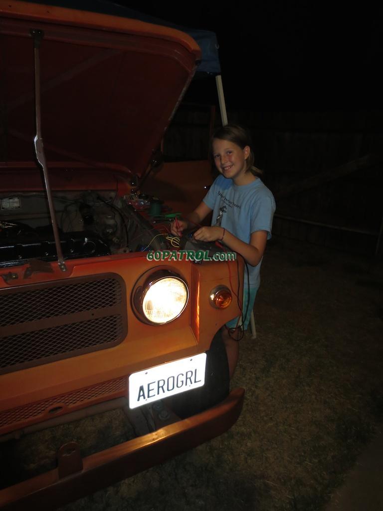
I propose the
Headlight Challenge! For research purposes anyway. I'm curious as to how much voltage drop others are seeing in their systems. If anyone is interested in the challenge, take six measurements and post the results so we can compare. With the engine running and the low beams on, take a voltage measurements at the big black wire on the upper corner of the fusebox
(main power feed from the battery) to ground
(I used the ground tied to the inner fender wall); then between the low-beam connection to ground on each headlight terminal strip. Next, repeat but for the high beams. Here's what ours showed this:
| Measurement Point | Low Beams On | High Beams On |
| Fusebox to Ground | 12.23v | 12.25v |
| Right Headlight to Gnd | 9.91v | 9.24v |
| Left Headlight to Gnd | 9.78v | 9.19v |
Note that ours will likely be quite different (lower) than yours as our engine is still on the operating table -- I did have a charger hooked up, but I'm sure the headlamps were feeling power starved! With a good generator/alternator, your baseline should be around 14v if I'm not mistaken. Anyway, I think it will be interesting to see the variations in the different vintages of Patrol wiring harnesses.
John
Re: 1967 Family Patrol Project
Posted: Wed Aug 20, 2014 2:39 pm
by Coyote Patrol
Your pushrods should be showing up soon.

Re: 1967 Family Patrol Project
Posted: Wed Aug 20, 2014 11:48 pm
by faux40
I got a whole bunch of packages today... Including one that I suspect contains the push rods! Thanks!
John
Re: 1967 Family Patrol Project
Posted: Thu Aug 21, 2014 10:26 am
by faux40
While playing with the headlights, I'd been just tossing around the old photocopied schematic that came with the orange Patrol. I'd assumed that I had an electronic copy to reprint it from. This morning, I wanted to print another copy to scribble on when I realized that I hadn't seen it anywhere else (perhaps it's there and I'm blind?). I think it's pretty special! The unusual thing is that it includes the wire gauges for each of the wires in metric units! It must be a schematic for the earlier Patrols as it shows positive ground -- What year did they change to neg. ground?
The metric size is listed to the right of each color code. For example a 0.85 sq.mm. green wire with a white stripe is labeled "gw 0.85". This is almost exactly a AWG 18 gauge wire (although I would replace it with a 16 gauge wire  )
)

In order to make sense of the wire sizes, I downloaded an AWG to Metric conversion chart. Since it didn't contain the exact gauges labeled on the chart... I added them. Anyway, here it is:
The wire sizes used in the schematic are highlighted in yellow.

Re: 1967 Family Patrol Project
Posted: Thu Aug 21, 2014 10:38 am
by Esteban
Re: 1967 Family Patrol Project
Posted: Thu Aug 21, 2014 10:58 am
by faux40
I wanted to, but it appears that I'm not authorized to upload PDFs... so I converted it to a jpg.
Oh admins! Can you help?
Thanks!
John
Re: 1967 Family Patrol Project
Posted: Thu Aug 21, 2014 11:03 am
by RiverPatrol
That's an excellent wiring diagram. I have never seen that one before either. It must be a very early one, possibly from an owner's manual. I could check some early service manuals that I have. Very nice!

Re: 1967 Family Patrol Project
Posted: Thu Aug 21, 2014 11:24 am
by bosque
This could be something I sent you. I have a giant copy of this. It is in a big text copy from the guy I bought some stuff off of.
Sent in email......they need to be merged.
Re: 1967 Family Patrol Project
Posted: Fri Aug 22, 2014 9:59 pm
by faux40
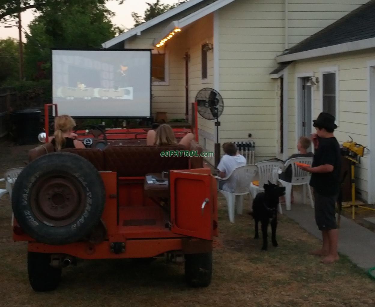
End of the summer drive-in movie night kicks off with cartoons... and glare free viewing thanks to the fold-down windshield!